


Foundation Formwork Systems
")
")
")
")
")
Assembly instructions for type FS 2001 and type FS 2001 G
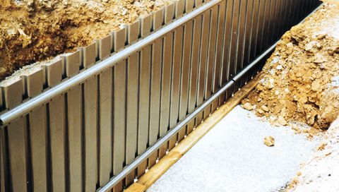
There are several ways to install the MSL casing system, depending on the local conditions. The trapezoid-profiled models FS 2001 and FS 2001 G, for example, can be erected as in the following photos 1-5. This version makes it easier to insert the spacer.
- Photo 1:
The casing element should be placed flat on the outside, then the lower brackets are to be fit into the profiling. - Photo 2:
After you have tipped the casing at a 90 degree angle, it should stand on the lower brackets without additional help (Then the reinforcement can be attached). - Photo 3:
The casing element is standing. - Photo 4:
The 2nd element is fit into place. - Photo 5:
Finally, the upper press-in brackets are fit into place. They keep the lateral sections fixed at the prescribed distance.